Back
BackProblem 3
At a given instant, a 2.4-A current flows in the wires connected to a parallel-plate capacitor. What is the rate at which the electric field is changing between the plates if the square plates are 1.60 cm on a side?
Problem 4
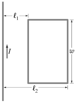
(III) A long straight wire and a small rectangular wire loop lie in the same plane, Fig. 30–25. Determine the mutual inductance in terms of 𝓁₁, 𝓁₂, and w. Assume the wire is very long compared to 𝓁₁, 𝓁₂, and w, and that the rest of its circuit is very far away compared to 𝓁₁, 𝓁₂, and w.
Problem 7
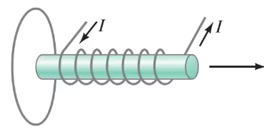
(II) If the solenoid in Fig. 29–47 is being pulled away from the loop shown, in what direction is the induced current in the loop? Explain.
Problem 9
A coil has 3.25-Ω resistance and 440-mH inductance. If the current is 3.00 A and is increasing at a rate of 3.15 A/s, what is the potential difference across the coil at this moment?
Problem 10
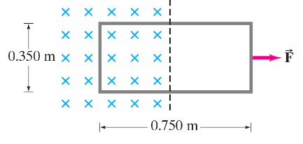
(II) Part of a single rectangular loop of wire with dimensions shown in Fig. 29–49 is situated inside a region of uniform magnetic field of 0.650 T. The total resistance of the loop is 0.250 Ω. Calculate the force required to pull the loop from the field (to the right) at a constant velocity of 3.40 m/s. Neglect gravity.
Problem 13
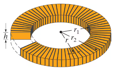
(III) A toroid has a rectangular cross section as shown in Fig. 30–26. Show that the self-inductance is
where N is the total number of turns and r₁, r₂ and h are the dimensions shown in Fig. 30–26. [Hint: Use Ampère’s law to get B as a function of r inside the toroid, and integrate.]
Problem 14
The magnetic field inside an air-filled solenoid 38.0 cm long and 2.10 cm in diameter is 0.720 T. Approximately how much energy is stored in this field?
Problem 16
What is the energy density at the center of a circular loop of wire carrying a 19.0-A current if the radius of the loop is 28.0 cm?
Problem 18
(II) For the toroid of Fig. 30–26, determine the energy density in the magnetic field as a function of r(r₁ < r < r₂) and integrate this over the volume to obtain the total energy stored in the toroid, which carries a current I in each of its N loops.
<IMAGE>
Problem 22
(III) Determine the emf induced in the square loop in Fig. 29–52 if the loop stays at rest and the current in the straight wire is given by I(t) = (15.0 A) sin (2200 t) where t is in seconds. The distance a is 12.0 cm, and b is 15.0 cm.
Problem 23
(II) (a) Determine the energy stored in the inductor L as a function of time for the LR circuit of Fig. 30–6a. (b) After how many time constants does the stored energy reach 99.9% of its maximum value?
Problem 25
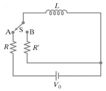
(II) (a) In Fig. 30–28, assume that the switch has been in position A for sufficient time so that a steady current I₀ = V₀/R flows through the resistor R. At time t = 0, the switch is quickly switched to position B and the current decays through resistor R' (which is much greater than R) according to . Show that the maximum emf εmax induced in the inductor during this time period is (R'/R)Vo. (b) If R' = 45R and Vo = 145 V, determine εmax. [When a mechanical switch is opened, a high-resistance air gap is created, which is modeled as R' here. This Problem illustrates why high-voltage sparking can occur if a current-carrying inductor is suddenly cut off from its power source. The very high voltage can produce an electric field great enough to ionize atoms of air, which emit light when electrons recombine with the ions.]
Problem 27
Two tightly wound solenoids have the same length and circular cross-sectional area. But solenoid 1 uses wire that is 1.5 times as thick as solenoid 2.
(a) What is the ratio of their inductances?
(b) What is the ratio of their inductive time constants? (Assume the only resistance in the circuits is that of the wire itself.)
Problem 27b
Two tightly wound solenoids have the same length and circular cross-sectional area. But solenoid 1 uses wire that is 1.5 times as thick as solenoid 2. What is the ratio of their inductive time constants? (Assume the only resistance in the circuits is that of the wire itself.)
Problem 28
(II) Suppose that the U-shaped conductor and connecting rod in Fig. 29–12a are oriented vertically (but still in contact) so that the rod is falling due to the gravitational force. Find the terminal speed of the rod if it has mass m = 3.6 grams, length 𝓁 = 18 cm, and resistance R = 0.0013 Ω. It is falling in a uniform horizontal field B = 0.080 T. Neglect the resistance of the U-shaped conductor, and friction.
Problem 30.52
(II) A 25-mH coil whose resistance is 0.80 Ω is connected to a capacitor C and a 420-Hz source voltage. If the current and voltage are to be in phase, what value must C have?
Problem 41
(II) A capacitor is placed in parallel with some device, B, as in Fig. 30–18b, to filter out stray high-frequency signals, but to allow ordinary 60.0-Hz ac to pass through with little loss. Suppose that circuit B in Fig. 30–18b is a resistance R = 530 Ω connected to ground, and that C = 0.35 μF. Calculate the ratio of the capacitor’s current amplitude to the incoming current’s amplitude if the incoming current has a frequency of (a) 60.0 Hz; (b) 60.0 kHz.
Problem 43
A 10.0-k Ω resistor is in series with a 34.0-mH inductor and an ac source. Calculate the impedance of the circuit if the source frequency is (a) 55.0 Hz; (b) 55.0 kHz.
Problem 47
A 1.50-k Ω resistor in series with a 370-mH inductor is driven by an ac power supply. At what frequency is the impedance double that of the impedance at 60.0 Hz?
Problem 48
An ac voltage source is connected in series with a 2.0-μF capacitor and a 750-Ω resistor. Using a digital ac voltmeter, the voltage source is measured to be 4.0 V rms, and the voltages across the resistor and across the capacitor are found to be 3.0 V rms and 2.7 V rms, respectively. Determine the frequency of the ac voltage source. Why is the voltage measured across the voltage source not equal to the sum of the voltages measured across the resistor and across the capacitor?
Problem 51b
An average power output of 150 W is sent into a 4-Ω loudspeaker (see Fig. 25–14). What are the rms voltage and the rms current fed to the speaker at 1.0 W when the volume is turned down?
Problem 60
The frequency of the ac voltage source (peak voltage Vo) in an LRC circuit is tuned to the circuit’s resonant frequency f₀ = 1 / (2π√LC). (a) Show that the peak voltage across the capacitor is Vco = VoTo/ (2πτ), where To ( =1/fo) is the period of the resonant frequency and τ = RC is the time constant for charging the capacitor C through a resistor R. (b) Define β = To/ (2πτ) so that Vco = βVo. Then β is the “amplification” of the source voltage across the capacitor. If a particular LRC circuit contains a 2.0-nF capacitor and has a resonant frequency of 5.0 kHz, what value of R will yield β = 125?
Problem 62a
(II) (a) Show that oscillation of charge Q on the capacitor of an LRC circuit has amplitude
Problem 65
The output of an electrocardiogram amplifier has an impedance of 45 Ω. It is to be connected to an 8.0-Ω loudspeaker through a transformer. What should be the turns ratio of the transformer?
Problem 66
Show that the power delivered by a three-phase ac source equals a constant P = 3Vo²/2R, by combining the four equations in Section 30–11.
Problem 67
At t = 0, the current through a 60.0-mH inductor is 50.0 mA and is increasing at the rate of 78.0 mA/s. What is the initial energy stored in the inductor, and how long does it take for the energy to increase by a factor of 8.0 from the initial value?
Problem 68
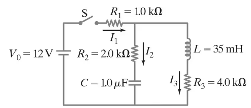
At time t = 0, the switch in the circuit shown in Fig. 30–30 is closed. After a sufficiently long time, steady currents I₁, I₂, and I₃ flow through resistors R₁, R₂, and R₃, respectively. Determine these three currents.
Problem 70
A pair of straight parallel thin wires, such as a lamp cord, each of radius r, are a distance 𝓁 apart and carry current to a circuit some distance away. Ignoring the field within each wire, show that the inductance per unit length is (μ₀/π) ln[(𝓁 - r) /r].
Problem 72a
For an underdamped LRC circuit, determine a formula for the energy U = UE + UB stored in the electric and magnetic fields as a function of time. Give answer in terms of the initial charge Qo on the capacitor.
Problem 78
An ac voltage source V = Vo sin (ωt + 90°) is connected across an inductor L and current I = Io sin (ωt) flows in this circuit. Note that the current and source voltage are 90° out of phase.
(a) Directly calculate the average power delivered by the source over one period T of its sinusoidal cycle via the integral P = ∫₀ᵀ VI dt/T.
(b) Apply the relation P = Iᵣₘₛ Vᵣₘₛ cos Φ to this circuit and show that the answer you obtain is consistent with that found in part (a). Comment on your results.