Back
BackProblem 13
Neglect the internal resistance of a battery unless the problem refers to it. Eight bulbs are connected in parallel to a 120-V source by two long leads of total resistance 1.4 Ω. If 210 mA flows through each bulb, what is the resistance of each, and what fraction of the total power is wasted in the leads?
Problem 16a
[In these Problems neglect the internal resistance of a battery unless the Problem refers to it.]
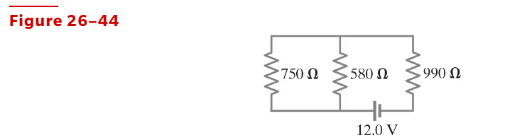
(II) Determine the equivalent resistance of the circuit shown in Fig. 26–44,
Problem 16b
[In these Problems neglect the internal resistance of a battery unless the Problem refers to it.]
(II) Determine the voltage across each resistor
Problem 16c
[In these Problems neglect the internal resistance of a battery unless the Problem refers to it.]
(II) Determine the current through each resistor.
Problem 18
[In these Problems neglect the internal resistance of a battery unless the Problem refers to it.]
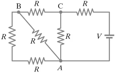
(II) What is the net resistance of the circuit connected to the battery in Fig. 26–46?
Problem 20
[In these Problems neglect the internal resistance of a battery unless the Problem refers to it.]
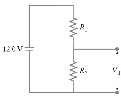
(II) A power supply has a fixed output voltage of 12.0 V, but you need VT = 3.0 V output for an experiment. (a) Using the voltage divider shown in Fig. 26–47, what should R₂ be if R₁ is 16.5 Ω? (b) What will the terminal voltage VT be if you connect a load to the 3.0-V output, assuming the load has a resistance of 7.0Ω?
Problem 26
[In these Problems neglect the internal resistance of a battery unless the Problem refers to it.]
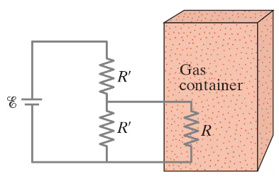
(III) You are designing a wire resistance heater to heat an enclosed container of gas. For the apparatus to function properly, this heater must transfer heat to the gas at a very constant rate. While in operation, the resistance of the heater will always be close to the value R = R₀, but may fluctuate slightly causing its resistance to vary a small amount ∆R ( << R₀ ). To maintain the heater at constant power, you design the circuit shown in Fig. 26–50, which includes two resistors, each of resistance R′. Determine the value for R′ so that the heater power P will remain constant even if its resistance R fluctuates by a small amount. [Hint: If ∆R << R₀ , then ]
Problem 26.39
(III) If the 25-Ω resistor in Fig. 26–59 is shorted out (resistance = 0 ), what then would be the current through the 15-Ω resistor?
Problem 31
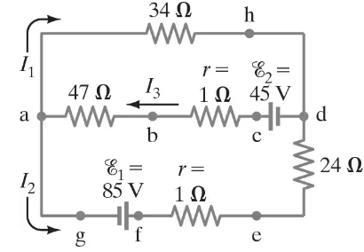
(II) (a) What is the potential difference between points a and d in Fig. 26–55 (similar to Fig. 26–12, Example 26–8), and (b) what is the terminal voltage of each battery?
Problem 34
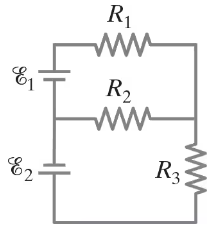
(II) Determine the magnitudes and directions of the currents in each resistor shown in Fig. 26–57. The batteries have emfs of ε1 = 9.0V and ε2 = 12.0V and the resistors have values of R1 = 25 Ω, R2 = 48 Ω, and R3 = 35 Ω.
(a) Ignore internal resistance of the batteries.
(b) Assume each battery has internal resistance r = 1.0 Ω.
Problem 35
A voltage V is applied to n identical resistors connected in parallel. If the resistors are instead all connected in series with the applied voltage, show that the power transformed is decreased by a factor n².
Problem 36
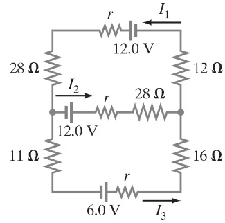
(III) (a) Determine the currents I1, I2, and I3 in Fig. 26–58. Assume the internal resistance of each battery is r = 1.0 Ω.
(b) What is the terminal voltage of the 6.0-V battery?
Problem 41
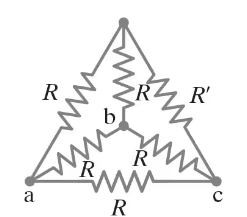
(III) Determine the net resistance in Fig. 26–61 (a) between points a and c, and (b) between points a and b. Assume R' ≠ R. [Hint: Apply an emf between the two points in each case and determine currents; use symmetry at junctions.]
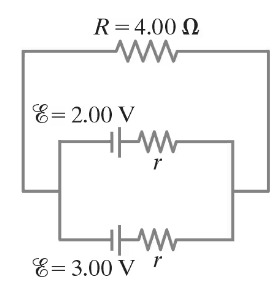
Problem 43
(II) Suppose two batteries, with unequal emfs of 2.00 V and 3.00 V, are connected as shown in Fig. 26–63. If each internal resistance is r = 0.350Ω and R = 4.00Ω, what is the voltage across the resistor R?
Problem 57a
A galvanometer has a sensitivity of 45kΩ/V and internal resistance 20.0 Ω. How could you make this into an ammeter that reads 1.0 A full scale?
Problem 58a
A galvanometer has an internal resistance of 32 Ω and deflects full scale for a 48-μA current. Describe how to use this galvanometer to make an ammeter to read currents up to 25 A.
Problem 58b
A galvanometer has an internal resistance of 32 Ω and deflects full scale for a 48-μA current. Describe how to use this galvanometer to make a voltmeter to give a full scale deflection of 250 V.
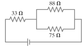
Problem 78
In the circuit shown in Fig. 26–75, the 33-Ω resistor dissipates 0.80 W. What is the battery voltage?
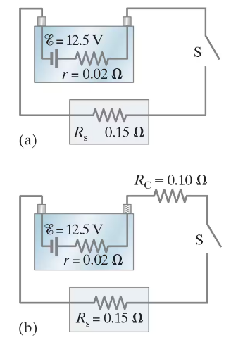
Problem 94
The performance of the starter circuit in a car can be significantly degraded by a small amount of corrosion on a battery terminal. Figure 26–88a depicts a properly functioning circuit with a battery (12.5-V emf, 0.02-Ω internal resistance) attached via corrosion-free cables to a starter motor of resistance Rs = 0.15Ω. Sometime later, corrosion between a battery terminal and a starter cable introduces an extra series resistance of only RC = 0.10Ω into the circuit as suggested in Fig. 26–88b. Let P0 be the power delivered to the starter in the circuit free of corrosion, and let P be the power delivered to the starter with corrosion. Determine the ratio P/P0.
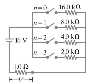
Problem 95
The circuit shown in Fig. 26–89 is a primitive 4-bit digital-to-analog converter (DAC). In this circuit, to represent each digit (2n) of a binary number, a “1” has the nᵗʰ switch closed whereas zero (“0”) has the switch open. For example, 0010 is represented by closing switch n = 1, while all other switches are open. Show that the voltage V across the 1.0 - Ω resistor for the binary numbers 0001, 0010, 0100, and 1010 (which represent 1, 2, 4, 10) follows the pattern that you expect for a 4-bit DAC.
Problem 99
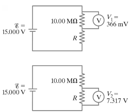
Measurements made on circuits that contain large resistances can be confusing. Consider a circuit powered by a battery ε = 15.000 V with a 10.00-MΩ resistor in series with an unknown resistor R. As shown in Fig. 26–92, a particular voltmeter reads V1 = 366 mV when connected across the 10.00 -MΩ resistor and this meter reads V2 = 7.317 V when connected across R. Determine the value of R. [Hint: Define RV as the voltmeter’s internal resistance.]
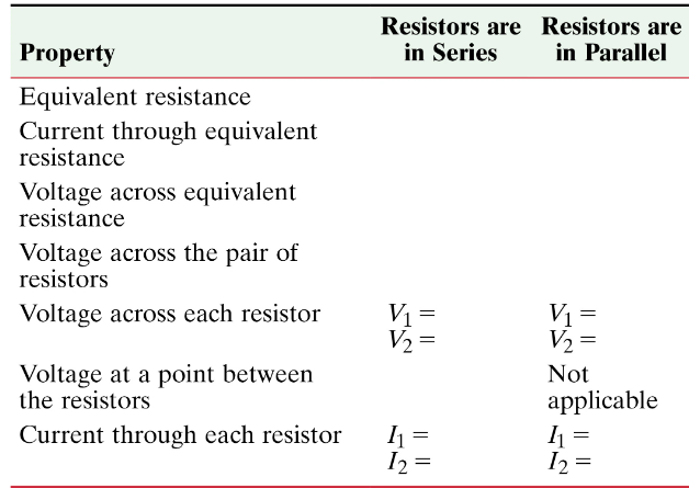
Problem 101
Consider two unequal resistors, of resistance R1 and R2, that are connected either in series or in parallel. Fill in the Table below assuming the electric potential on the low-voltage end of the combination is VA volts and the potential at the high-voltage end of the combination is VB volts. First draw diagrams.