Back
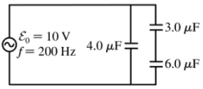
BackProblem 42a
What is the peak current supplied by the emf in FIGURE P32.42?
Problem 42b
What is the peak voltage across the 3.0 μF capacitor?
Problem 43a
For an RC circuit, find an expression for the angular frequency at which VR = ½ ε0.
Problem 43b
For an RC circuit, find an expression for the angular frequency at which VR = ½ ε0. What is VC at this frequency?
Problem 45
A series RC circuit is built with a 12 kΩ resistor and a parallel-plate capacitor with 15-cm-diameter electrodes. A 12 V, 36 kHz source drives a peak current of 0.65 mA through the circuit. What is the spacing between the capacitor plates?
Problem 46
You have a resistor and a capacitor of unknown values. First, you charge the capacitor and discharge it through the resistor. By monitoring the capacitor voltage on an oscilloscope, you see that the voltage decays to half its initial value in 2.5 ms. You then use the resistor and capacitor to make a low-pass filter. What is the crossover frequency fc?
Problem 48
The small transformers that power many consumer products produce a 12.0 V rms, 60 Hz emf. Design a circuit using resistors and capacitors that uses the transformer voltage as an input and produces a 6.0 V rms output that leads the input voltage by 45°.
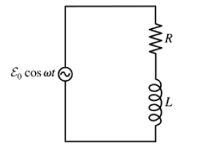
Problem 49a
Use a phasor diagram to analyze the RL circuit of FIGURE P32.49. In particular, Find expressions for I, VR, and VL.
Problem 49b
Use a phasor diagram to analyze the RL circuit of FIGURE P32.49. In particular, What is VR in the limits ω→0 and ω→∞?
Problem 49d
Use a phasor diagram to analyze the RL circuit of FIGURE P32.49. In particular, Find an expression for the crossover frequency ωc.
Problem 50
A series RL circuit is built with a 110 Ω resistor and a 5.0-cm-long, 1.0-cm-diameter solenoid with 800 turns of wire. What is the peak magnetic flux through the solenoid if the circuit is driven by a 12 V, 5.0 kHz source?
Problem 51a
A series RLC circuit consists of a 75 Ω resistor, a 0.12 H inductor, and a 30 μF capacitor. It is attached to a 120 V/60 Hz power line. What is the peak current I?
Problem 51b
A series RLC circuit consists of a 75 Ω resistor, a 0.12 H inductor, and a 30 μF capacitor. It is attached to a 120 V/60 Hz power line. What is the phase angle ϕ?
Problem 51c
A series RLC circuit consists of a 75 Ω resistor, a 0.12 H inductor, and a 30 μF capacitor. It is attached to a 120 V/60 Hz power line. What is the average power dissipated?
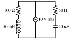
Problem 54
In FIGURE P32.54, what is the current supplied by the emf when (a) the frequency is very small and (b) the frequency is very large?
Problem 55a
A series RLC circuit consists of a 50 Ω resistor, a 3.3 mH inductor, and a 480 nF capacitor. It is connected to a 5.0 kHz oscillator with a peak voltage of 5.0 V. What is the instantaneous current i when ε = ε0?
Problem 58
Show that the power factor of a series RLC circuit is cos ϕ=R/Z.
Problem 60a
The tuning circuit in an FM radio receiver is a series RLC circuit with a 0.200 μH inductor. The receiver is tuned to a station at 104.3 MHz. What is the value of the capacitor in the tuning circuit?
Problem 60b
The tuning circuit in an FM radio receiver is a series RLC circuit with a 0.200 μH inductor. FM radio stations are assigned frequencies every 0.2 MHz, but two nearby stations cannot use adjacent frequencies. What is the maximum resistance the tuning circuit can have if the peak current at a frequency of 103.9 MHz, the closest frequency that can be used by a nearby station, is to be no more than 0.10% of the peak current at 104.3 MHz? The radio is still tuned to 104.3 MHz, and you can assume the two stations have equal strength.
Problem 61a
A television channel is assigned the frequency range from 54 MHz to 60 MHz. A series RLC tuning circuit in a TV receiver resonates in the middle of this frequency range. The circuit uses a 16 pF capacitor. What is the value of the inductor?
Problem 63a
Commercial electricity is generated and transmitted as three-phase electricity. Instead of a single emf, three separate wires carry currents for the emfs ε1 = ε0 cos ωt, ε2 = ε0 cos(ωt +120°), and ε3 = ε0 cos(ωt−120°) over three parallel wires, each of which supplies one-third of the power. This is why the long-distance transmission lines you see in the countryside have three wires. Suppose the transmission lines into a city supply a total of 450 MW of electric power, a realistic value. What would be the rms current in each wire if the transmission voltage were ε0 = 120 V rms?
Problem 63b
Commercial electricity is generated and transmitted as three-phase electricity. Instead of a single emf, three separate wires carry currents for the emfs ε1 = ε0 cos ωt, ε2 = ε0 cos(ωt +120°), and ε3 = ε0 cos(ωt−120°) over three parallel wires, each of which supplies one-third of the power. This is why the long-distance transmission lines you see in the countryside have three wires. Suppose the transmission lines into a city supply a total of 450 MW of electric power, a realistic value. In fact, transformers are used to step the transmission-line voltage up to 500 kV rms. What is the current in each wire?
Problem 64
A generator consists of a 12-cm by 16-cm rectangular loop with 500 turns of wire spinning at 60 Hz in a 25 mT uniform magnetic field. The generator output is connected to a series RC circuit consisting of a 120 Ω resistor and a 35 μF capacitor. What is the average power delivered to the circuit?
Problem 65a
You're the operator of a 15,000 V rms, 60 Hz electrical substation. When you get to work one day, you see that the station is delivering 6.0 MW of power with a power factor of 0.90. What is the rms current leaving the station?
Problem 66c
Commercial electricity is generated and transmitted as three-phase electricity. Instead of a single emf ε = ε0 cos ωt, three separate wires carry currents for the emfs ε1 = ε0 cos ωt, ε2 = ε0 cos(ωt+120°), and ε3 = ε0 cos(ωt−120°). This is why the long-distance transmission lines you see in the countryside have three parallel wires, as do many distribution lines within a city. Show that the potential difference between any two of the phases has the rms value 3–√ εrms, where εrms is the familiar single-phase rms voltage. Evaluate this potential difference for εrms = 120 V. Some high-power home appliances, especially electric clothes dryers and hot-water heaters, are designed to operate between two of the phases rather than between one phase and neutral. Heavy-duty industrial motors are designed to operate from all three phases, but full three-phase power is rare in residential or office use.
Problem 67b
A motor attached to a 120 V/60 Hz power line draws an 8.0 A current. Its average energy dissipation is 800 W. What is the rms resistor voltage?
Problem 67c
A motor attached to a 120 V/60 Hz power line draws an 8.0 A current. Its average energy dissipation is 800 W. What is the motor's resistance?
Problem 67d
A motor attached to a 120 V/60 Hz power line draws an 8.0 A current. Its average energy dissipation is 800 W. How much series capacitance needs to be added to increase the power factor to 1.0?
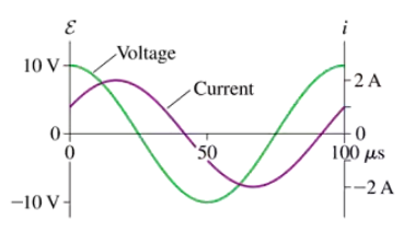
Problem 68a
FIGURE CP32.68 shows voltage and current graphs for a series RLC circuit. What is the resistance R?
Problem 69b
Prove that the energy dissipation is a maximum at ω = ω₀.