Back
BackProblem 51
A small, 2.0-mm-diameter circular loop with R = 0.020 Ω is at the center of a large 100-mm-diameter circular loop. Both loops lie in the same plane. The current in the outer loop changes from +1.0 A to −1.0 A in 0.10 s. What is the induced current in the inner loop?
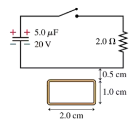
Problem 53b
A rectangular metal loop with 0.050 Ω resistance is placed next to one wire of the RC circuit shown in FIGURE P30.53. The capacitor is charged to 20 V with the polarity shown, then the switch is closed at t = 0 s. What is the current in the loop at t = 5.0 μs? Assume that only the circuit wire next to the loop is close enough to produce a significant magnetic field.
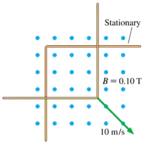
Problem 54a
CALC The L-shaped conductor in FIGURE P30.54 moves at 10 m/s across and touches a stationary L-shaped conductor in a 0.10 T magnetic field. The two vertices overlap, so that the enclosed area is zero, at t = 0 s. The conductor has a resistance of 0.010 ohms per meter. a. What is the direction of the induced current?
Problem 55a
INT A 20-cm-long, zero-resistance slide wire moves outward, on zero-resistance rails, at a steady speed of 10 m/s in a 0.10 T magnetic field. (See Figure 30.26.) On the opposite side, a 1.0 Ω carbon resistor completes the circuit by connecting the two rails. The mass of the resistor is 50 mg. What is the induced current in the circuit?
Problem 55b
INT A 20-cm-long, zero-resistance slide wire moves outward, on zero-resistance rails, at a steady speed of 10 m/s in a 0.10 T magnetic field. (See Figure 30.26.) On the opposite side, a 1.0 Ω carbon resistor completes the circuit by connecting the two rails. The mass of the resistor is 50 mg. How much force is needed to pull the wire at this speed?
Problem 55c
INT A 20-cm-long, zero-resistance slide wire moves outward, on zero-resistance rails, at a steady speed of 10 m/s in a 0.10 T magnetic field. (See Figure 30.26.) On the opposite side, a 1.0 Ω carbon resistor completes the circuit by connecting the two rails. The mass of the resistor is 50 mg. If the wire is pulled for 10 s, what is the temperature increase of the carbon? The specific heat of carbon is 710 J/kg K.
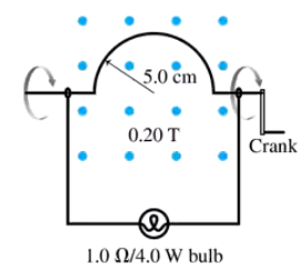
Problem 57a
CALC Your camping buddy has an idea for a light to go inside your tent. He happens to have a powerful (and heavy!) horseshoe magnet that he bought at a surplus store. This magnet creates a 0.20 T field between two pole tips 10 cm apart. His idea is to build the hand-cranked generator shown in FIGURE P30.57. He thinks you can make enough current to fully light a 1.0 Ω lightbulb rated at 4.0 W. That's not super bright, but it should be plenty of light for routine activities in the tent. Find an expression for the induced current as a function of time if you turn the crank at frequency f. Assume that the semicircle is at its highest point at t = 0 s.
Problem 57b
CALC Your camping buddy has an idea for a light to go inside your tent. He happens to have a powerful (and heavy!) horseshoe magnet that he bought at a surplus store. This magnet creates a 0.20 T field between two pole tips 10 cm apart. His idea is to build the hand-cranked generator shown in FIGURE P30.57. He thinks you can make enough current to fully light a 1.0 Ω lightbulb rated at 4.0 W. That's not super bright, but it should be plenty of light for routine activities in the tent. With what frequency will you have to turn the crank for the maximum current to fully light the bulb? Is this feasible?
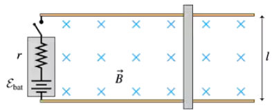
Problem 58a
INT You've decided to make the magnetic projectile launcher shown in FIGURE P30.58 for your science project. An aluminum bar slides along metal rails through a magnetic field B. The switch closes at t = 0 s, while the bar is at rest, and a battery of emf εbat starts a current flowing around the loop. The battery has internal resistance r. The resistances of the rails, which are separated by distance l, and the bar are effectively zero. Show that the bar reaches a terminal speed vterm, and find an expression for vterm.
Problem 58b
INT You've decided to make the magnetic projectile launcher shown in FIGURE P30.58 for your science project. An aluminum bar slides along metal rails through a magnetic field B. The switch closes at t = 0 s, while the bar is at rest, and a battery of emf εbat starts a current flowing around the loop. The battery has internal resistance r. The resistances of the rails, which are separated by distance l, and the bar are effectively zero. Evaluate vterm for εbat = 1.0 V, r = 0.10 Ω, l = 6.0 cm, and B = 0.50 T.
Problem 59b
INT FIGURE P30.59 shows a U-shaped conducting rail that is oriented vertically in a horizontal magnetic field. The rail has no electric resistance and does not move. A slide wire with mass m and resistance R can slide up and down without friction while maintaining electrical contact with the rail. The slide wire is released from rest. Determine the value of vterm if l = 20 cm,m = 10 g, R = 0.10 Ω, and B = 0.50 T.
Problem 62
One way to measure the strength of a magnetic field is with a flip coil. Suppose a 200-turn, 4.0-cm-diameter coil with a resistance of 2.0 Ω is connected to a ballistic galvanometer, a device that measures the total charge passing through. The coil is held perpendicular to the field, then quickly flipped 180° so that the opposite side is facing the magnetic field. Afterward, the galvanometer reads 7.5 μC. What is the field strength? Hint: Use I = dq/dt to relate the net change of flux to the amount of charge that flows through the galvanometer.
Problem 65
BIO One possible concern with MRI (see Exercise 28) is turning the magnetic field on or off too quickly. Bodily fluids are conductors, and a changing magnetic field could cause electric currents to flow through the patient. Suppose a typical patient has a maximum cross-section area of 0.060 m2. What is the smallest time interval in which a 5.0 T magnetic field can be turned on or off if the induced emf around the patient's body must be kept to less than 0.10 V?
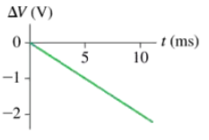
Problem 67
CALC FIGURE P30.67 shows the potential difference across a 20 mH inductor. The current through the inductor at t = 0 ms is 0.25 A. What is the current at t = 10 ms?
Problem 69a
A 50 cm solenoid with 1000 turns has an inductance of 20 mH. What is the magnetic field strength inside the inductor when the current is 75 mA?
Problem 69b
A 50 cm solenoid with 1000 turns has an inductance of 20 mH. Flipping a switch disconnects the inductor from the battery and connects it to a resistor. What is the value of the resistance if the magnetic field decreases by 50% in 150 μs?
Problem 70a
CALC The current through inductance L is given by . Find an expression for the potential difference ΔVL across the inductor.
Problem 70b
CALC The current through inductance L is given by . Evaluate ΔVL at t = 0, 1.0, and 3.0 ms if L = 20 mH, I0 = 50 mA, and = 1.0 ms.
Problem 71b
An LC circuit is built with a 20 mH inductor and an 8.0 pF capacitor. The capacitor voltage has its maximum value of 25 V at t = 0 s. What is the inductor current at that time?
Problem 72
An electric oscillator is made with a 0.10 μF capacitor and a 1.0 mH inductor. The capacitor is initially charged to 5.0 V. What is the maximum current through the inductor as the circuit oscillates?
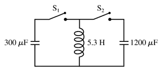
Problem 75a
The 300 μF capacitor in FIGURE P30.75 is initially charged to 100 V, the 1200 μF capacitor is uncharged, and the switches are both open. What is the maximum voltage to which you can charge the 1200 μF capacitor by the proper closing and opening of the two switches?
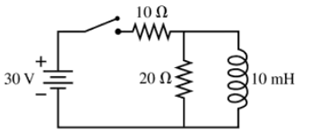
Problem 76a
The switch in FIGURE P30.76 has been open for a long time. It is closed at t = 0 s. What is the current through the 20 Ω resistor immediately after the switch is closed?
Problem 76b
The switch in FIGURE P30.76 has been open for a long time. It is closed at t = 0 s. What is the current through the 20 Ω resistor after the switch has been closed a long time?
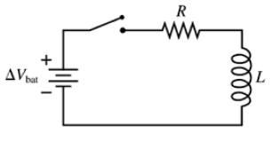
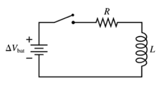
Problem 77a
The switch in FIGURE P30.77 has been open for a long time. It is closed at t = 0 s. After the switch has been closed for a long time, what is the current in the circuit? Call this current I0.
Problem 77b
The switch in FIGURE P30.77 has been open for a long time. It is closed at t = 0 s. Find an expression for the current I as a function of time. Write your expression in terms of I0, R, and L.
Problem 80
In recent years it has been possible to buy a 1.0 F capacitor. This is an enormously large amount of capacitance. Suppose you want to build a 1.0 Hz oscillator with a 1.0 F capacitor. You have a spool of 0.25-mm-diameter wire and a 4.0-cm-diameter plastic cylinder. How long must your inductor be if you wrap it with 2 layers of closely spaced turns?
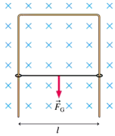
Problem 81
CALC The rectangular loop in FIGURE CP30.81 has 0.020 Ω resistance. What is the induced current in the loop at this instant?
Problem 83a
CALC Let's look at the details of eddy-current braking. A square loop, length l on each side, is shot with velocity v0 into a uniform magnetic field B. The field is perpendicular to the plane of the loop. The loop has mass m and resistance R, and it enters the field at t = 0 s. Assume that the loop is moving to the right along the x-axis and that the field begins at x = 0 m. Find an expression for the loop's velocity as a function of time as it enters the magnetic field. You can ignore gravity, and you can assume that the back edge of the loop has not entered the field.
Problem 83b
CALC Let's look at the details of eddy-current braking. A square loop, length l on each side, is shot with velocity v0 into a uniform magnetic field B. The field is perpendicular to the plane of the loop. The loop has mass m and resistance R, and it enters the field at t=0 s. Assume that the loop is moving to the right along the x-axis and that the field begins at x = 0 m. Calculate and draw a graph of v over the interval 0 s ≤ t ≤ 0.04 s for the case that v0=10 m/s, l = 10 cm, m = 1.0 g, R = 0.0010 Ω, and B=0.10 T. The back edge of the loop does not reach the field during this time interval.
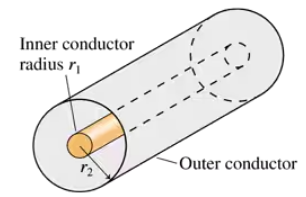
Problem 86b
CALC High-frequency signals are often transmitted along a coaxial cable, such as the one shown in FIGURE CP30.86. For example, the cable TV hookup coming into your home is a coaxial cable. The signal is carried on a wire of radius r1 while the outer conductor of radius r2 is grounded. A soft, flexible insulating material fills the space between them, and an insulating plastic coating goes around the outside. Evaluate the inductance per meter of a cable having r1 = 0.50 mm and r2 = 3.0 mm.